
|
1951 Buick Fuel and Vacuum Pump
DESCRIPTION AND OPERATION OF FUEL AND VACUUM PUMPThe AC type AJ combination fuel and vacuum pump is used on all series engines. The pump assembly for Series 70 Differs from the pump for Series 40-50 only in the shape of rocker arm and in the use of an air dome on the fuel outlet of the Series 70 pump.
The pump assembly, which is mounted on right side of engine crankcase at the front, is operated by an eccentric on the engine camshaft
The fuel and vacuum sections form two separate, independently operating diaphragm type pumps. They are combined in one assembly for compactness and to permit operation from one eccentric on the engine camshaft.
A fuel filter, consisting of a metal bowl and a fine mesh screen, is incorporated in the fuel
b. Operation of Fuel Section fo Pump.
The function of the fuel section of the pump is to draw gasoline from the tank and supply it to the carburetor in sufficient quantity to meet engine requirements at all speeds and loads.
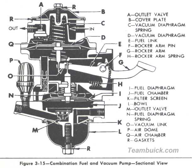
The pump rocker arm (G) is actuated by an eccentric on engine camshaft. The arm is held in contact with the eccentric by the rocker arm spring (H). Movement of rocker arm is transmitted to the fuel link (E) which pulls the fuel diaphragm (I) upward from the fuel chamber (J) against pressure of the diaphragm spring (N). See figure 3-15
Vacuum created in the fuel chamber by upward movement of diaphragm holds the outlet valve (M) closed and causes fuel to flow from the gasoline tank, through the inlet valve (not shown), into the fuel chamber.
The return stroke (low point of cam) releases the compressed diaphragm spring which then exerts pressure on the B and the fuel in the chamber. This pressure closes the inlet valve and forces fuel out through the outlet valve to the carburetor in an amount governed by the pressure in the pump-to-carburetor line.
The fuel link is hinged to the rocker arm so that the link and the connected fuel diaphragm can be moved up, but not down, by the rocker arm. The link and the B are moved downward only by the diaphrabB The pump, therefore, delivers fuel to the carburetor only when the fuel pressure in the outlet line is less than the pressure maintained by the diaphragm springBndition arises when the carburetor float needle valve is not seated and the fuel passage from the pump into the carburetor float chamber is open. When the needle valve is closed and held in place by the pressure of the fuel on the float, the pump builds up pressure of the fuel on the float, the pump builds up pressure in fuel chamber until it overcomes the pressure of the diaphragm spring. This pBesults in almost complete stoppage of stoppage movement until more fuel is needed. Normal diaphragm stroke is approximately 1/64".
c. Operation of Vacuum Section of Pump
The function of the vacuum section of the pump is to act as a booster to the intake manifold vacuum, thereby providing uniform operation of the windshield wiper at all engine speeds and loads.
The pump rocker arm (G) is actuated by an eccentric on engine camshaft. The arm is held in contact with the eccentric by the rocker arm spring (H). Movement of the rocker arm is transmitted to the vacuum link (O) which pushes vacuum diaphragm (D) upward into air chamber (Q) against pressure of the diaphragm spring (C). See figure 3-15
Pressure created in the air chamber by upward movement of diaphragm holds the inlet valve (not shown) closed and expels air through the outlet valve (A) into the engine manifold.
The return stroke (low point of cam) releases the compressed in spring which then pushes the diaphragm creating a vacuum in air chamber. This vacuum closes the outlet valve and draws air through the inlet valve from the windshield wiper.
The diaphragm operates only when engine vacuum is insufficient for windshield wiper action. When manifold vacuum is greater than that created by the pump, the stronger manifold vacuum pulls the diaphragm into the air chamber, holding the vacuum link out of engagement with the rocker arm. The windshield wiper then operates on manifold vacuum without assistance from the pump. When intake manifold vacuum is low, as on acceleration or at high speed, the vacuum created by the pump will assure adequate operation of the wiper.
3-15 FUEL PUMP INSPECTION AND TEST
If the fuel pump is suspected of delivering an improper amount of fuel to the carburetor, it should be inspected and tested as follows:
2. With the engine running, inspect for leaks at all gasoline feed pipe connections at gasoline tank, fuel pump, gasoline filter, and carburetor. Tighten any loose connections. Inspect the flexible connection in feed line and all pipes for dents or kinks which would restrict the flow of fuel. Air leaks or restrictions on suction side of fuel pump will seriously affect pump output.
3. Inspect for leaks at fuel pump H1 flange. Tighten the cover screws alternately and securely. Do not use shellac or any other adhesive on diaphragm.
4. Clean the filter in fuel pump and gasoline filter at carburetor and make sure that filter bowl gaskets are sealing securely.
5. Disconnect pump-to-carburetor pipe. Ground primary terminal of distributor with jumper wire so that engine can be cranked without firing. Place suitable container at end of pipe and crank engine a few revolutions. If no gasoline, or only a little, flows from pipe the feed pipes are clogged or fuel pump is inoperative. Before condemning the fuel pump, disconnect feed pipes at pump and blow through them with air hose to make sure that pipes are clear.
6. If gasoline flows in good volume from pipe at carburetor it may be assumed that the fuel pump and feed pipes are okay; however, it is advisable to make the following "static pressure" test to make certain that fuel pump is operating within specified pressure limits.
7. Attach a suitable pressure gauge to the disconnected end of gasoline pipe at carburetor. Run engine at 450 and 1000 rpm on gasoline in carburetor bowl and note reading on pressure gauge.
8. If fuel pump is operating properly the pressure will be 4 to 5 pounds and will remain constant at speeds between 450 and 1000 rpm. If pressure is too low or too high, or varies materially at different speeds, the pump should be removed for repairs. NOTE:If pressure gauge is connected at pump outlet instead of at end of feed pipe the pressure should be 41/2 to 51/2 pounds.
3-16 VACUUM PUMP INSPECTION AND TEST
To test the vacuum section of pump, fully open the windshield wiper valve and observe the wiper blade while alternately idling and
1. Check windshield wiper transmission cables to make sure they are correctly attached to wiper motor, are properly located in pulleys on wiper transmissions and cable tensioners, and are not rubbing against anything under the cowl. Make certain that wiper control hoses are properly connected at manifold, wiper motor, and control on instrument panel.
2. Check tightness of vacuum pump cover plate screw and check all pipe and hose connections between pump and windshield wiper motor. Tighten loose connections and replace any cracked or deteriorated hose.
3. If windshield wiper does not operate properly after all pints of leakage have been corrected, detach both pipes at vacuum pump and join them with a piece of rubber hose. Slowly operate engine from idle to about 25 MPH speed: the wiper should run at full speed operating on engine vacuum only. If it does not, it can be assumed that the wiper motor or tubing is defective. The pump vacuum section is inoperative if the windshield wiper operates properly on engine vacuum but not on pump vacuum.
4. A further test of vacuum pump may be made by attaching a vacuum gauge to the inlet port (port connected to wiper motor), with outlet pipe disconnected. CAUTION:Always make this test of vacuum pump with the outlet open. The downward or exhaust stroke of pump is positive and the mechanism may be damaged if the outlet is closed or restricted. 5. With engine operating at equivalent of 20 MPH road speed, the gauge should show 7 to 12 inches of vacuum. Less than 7 inches of vacuum indicates an inoperative vacuum pump.
6. Before removing the fuel and vacuum pump assembly for repairs to vacuum section, it is advisable to remove the cover plate and check condition of cover plate and screw gaskets, and condition of the screen under the cover plate. Leaking gaskets or a plugged screen would affect vacuum pump operation.
If only the vacuum pump requires replacement of the diaphragm or valves, the procedures given in subparagraphs a, c, and e, should be followed. If the fuel section of pump requires replacement of the diaphragm, however, the complete proceedure given in subparagraphs a through e must be followed.
The fuel diaphragm is sealed around the pull rod with a tight fitting oil seal which is staked into the pump body. Tilting of the diaphragm to unhook pull rod from the fuel link will damage this oil seal. The safest method to follow is to first remove the rocker arm and link so that diaphragm pull rod can be pulled straight out without damage to the seal.
The vacuum diaphragm should be removed before the fuel diaphragm and installed after the fuel diaphragm because the fuel diaphragm and link cannot be correctly assembled with the vacuum diaphragm connected to the vacuum links.
a. Removal of Vacuum Diaphragm and Valves
1. Plug all openings and thoroughly wash outside of the unit with cleaning solvent and blow off with air hose to remove all dirt and grease.
2. Mark edges of vacuum cover and pump body with edge of a file, so that cover may be reinstalled in its original position on body.
3. Remove only two cover screws from opposite sides of the cover, and substitute for them two No. 10-32 x 1 1/2" fillister head screws. Turn the two long screws all the way down, and then remove the balance of the short screws. Alternately back off the two long screws, a few turns at a time, until the force of the heavy vacuum diaphragm spring is no longer effective. If cover and body stick together, rap cover with screwdriver handle after backing off long screws a few turns; do not pry between the flanges. Remove long screws, vacuum cover assembly, diaphragm spring and spring retainer. See figure 3-15
7. If fuel section of pump is to be repaired also, proceed with subparagraph b; otherwise, inspect parts removed (subpar. c) and re-assemble vacuum section with necessary new parts (subpar. e)
b. Removal of Fuel Diaphragm and Valves
1. Mark edges of fuel cover and pump body with edge of a file, so that cover may be reinstalled in its original position on body.
2. Remove fuel cover screws and separate the cover from pump body by rapping with screwdriver handle; do not pry between flanges.
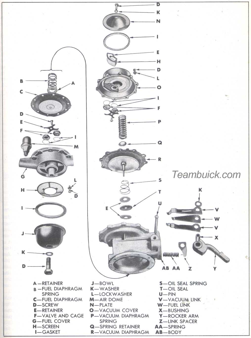
3. Remove bowl and gasket, screen, valve retainer and valves from fuel cover. See figure 3-16.
4. File riveted end of rocker arm pin flush with steel washer, or cut off end with 3/8" drill, then drive out rocker arm pin with a drift punch. Wiggle rocker arm until link unhooks from fuel drill, then remove rocker arm and link assembly, and rocker arm spring.
5. Remove fuel drill from body by pulling straight out. CAUTION:Do not tilt excessively or staked-in oil seal in pump body will be damaged. Remove drill spring and spring retainer.
6. Remove bushing from rocker arm to disassemble rocker arm, two vacuum links, one fuel link, link spacer, and link washers (there may be one or two link washers). See figure 3-16.
c. Cleaning and Inspection of Pump Parts
Replacement parts are available in three different kits, as follows:
- Vacuum Pump Diaphragm Kit
- Fuel Pump Diaphragm Kit
- Overhaul Kit
Each diaphragm kit contains the proper diaphragm, valves, springs, and gaskets to service the indicated section of the pump. A separate rocker arm pin is required with the fuel pump diaphragm kit. The overhaul kit contains all parts in both diaphragm kits plus links and other parts subject to wear or deterioration.
The kit to use will be determined by the corrections required, or by inspection fo disassembled parts as follows:
1. Clean and rinse all metal parts in solvent. Blow out all passages with air hose.
2. Inspect pump body, fuel , and vacuum covers for cracks, breakable, and distorted
3. Inspect rocker arm for wear or scores at camshaft pad, at point of contact with links, and at pivot hole.
4. Inspect screws and replace if damaged or obstructed. Screws must fit snugly into recesses around all edges.
5. Replace links if pump has been in service for high mileage. Amount of wear cannot be determined visually.
6. Replace diaphragm in faulty section of pump, or both diaphragms if service mileage is high.
7. Replace valve and cage assemblies as these parts cannot be visually checked for wear.
8. Replace rocker arm and diaphragm springs, as removed, because old springs may be distorted or corroded.
9. Replace rocker arm pin and washer if removed, as these cannot be used again.
10. Always replace all gaskets removed, to insure tight seals.
D. Installation of Fuel Diaphragm and Valves
Always install the fuel diaphragm before the vacuum diaphragm
1. Soak new fuel diaphragm in clean kerosene while performing the following steps. Fuel oil or gasoline may be used.
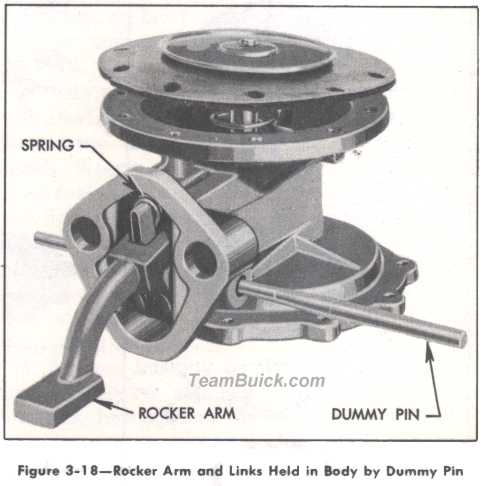
2. Insert drilled end of fuel link (short) into link spacer. Place one vacuum link (long) on each side of spacer so that the hooked ends of long links come together. The hooked ends of all links and the projection on link spacer must point as shown in figure 3-18
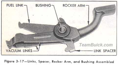
3. Line up the holes in links and spacer, slide parts between the jaws of rocker arm with flat surface of rocker arm pad facing in same direction as link hooks, then install the pin bushing. See figure 3-17.
5. Stand the pump body on the bench, fuel flange down. Set rocker arm spring in body with one end over cone cast into body. Slide rocker arm and link assembly into body, with open end of all link hooks pointing up toward vacuum flange, and engage rocker arm spring with projection on link spacer. Hold parts in body with the small end of Rocker Arm Dummy Pin KMO-707 (AC No. PT-6. See figure 3-18.
6. Turn the pump body over so the fuel diaphragm flange is up. Set the diaphragm spring on the staked-in oil seal, and the retainer on top of the spring. Push diaphragm pull rod through retainer, spring and oil seal. Flat of pull rod must be at right angles to link. Hook diaphragm pull rod to the short center fuel link. CAUTION Do not tilt diaphragm pull rod excessively as this may damage the oil seal.
7. Push Dummy Pin through body so that large diameter aligns the holes in all parts, then drive the pin out with the new permanent rocker arm pin.
8. Support head of rocker arm pin on a suitable steel block, place washer over small end of pin so it lies flat against body, then spread or "mushroom" end of pin with a ball peen hammer.
9. Place one gasket in each valve seat in fuel cover. Place one valve in seat nearest the outlet port with the three legged spider down. Place
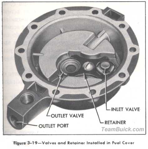
another valve in other seat with spider facing up. Place retainer over valves with humped side up and install retainer screw. See figure 3-19.
10. Install gasoline screen, bowl gasket and bowl in the order named, then install bowl screw and gasket and tighten screw securely.
11. A diaphragm gasket (not used in factory assembly) is included in each repair parts kit. Its purpose is to compensate for slight warpage of the fuel cover flange that may occur in service. Place this gasket on the fuel diaphragm and align all screw holes in gasket, diaphragm, and pump body.
NOTE:Holes may be kept in alignment and possible distortion of diaphragm may be avoided by making two guide pins with short 10-32 threads and temporarily installing these in opposite screw holes in body flange.
12. Place fuel cover in position so that file marks on cover and pump body are in line, maintain pressure on rocker arm so that diaphragm is flat across body flange, then install all cover screws and lock washers until screws just engage lock washers. Be sure that screws pass through holes in fabric of diaphragm without chewing.
13. Pump rocker arm two or three full strokes to make sure that diaphragm is not stretched too tight, then hold arm to fully compress the diaphragm spring while tightening cover screws. Tighten screws alternately on diametrically opposite sides until all are tight before releasing the rocker arm.
CAUTION:Diaphragm must be held in flexed position until all screws are tightened,
e. Installation of Vacuum Diaphragm and Valves
1. Soak new vacuum diaphragm in clean kerosene while performing the following steps. Fuel oil or gasoline may be used.
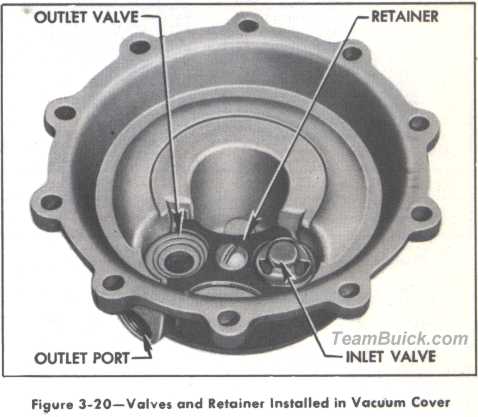
2. Place one gasket in each valve seat in vacuum cover. Place one valve in seat adjacent to outlet port with the three legged spider down. Place another valve in other seat with spider facing up. Place retainer over valves with humped side up and install retainer screw. See figure 3-30.
3. Turn cover over, and set screen in recess over valve hole. Set screen retainer on screen. Place cover plate gasket, cover plate, screw gasket, and cover plate screw in position in the order named. Tighten cover screw.
4. Install oil seal parts on vacuum diaphragm pull rod in the following order: spring, retainer, oil seal, and retainer. Turn outer retainer to lock parts on pull rod.
5. Hold pump with fuel side up so that vacuum links will drop into position for attaching vacuum diaphragm pull rod. Insert diaphragm pull rod through opening in pump body and hook it to the two long vacuum links.
6. Hold vacuum diaphragm in place while clamping pump body mounting flange in a vice, with diaphragm up.
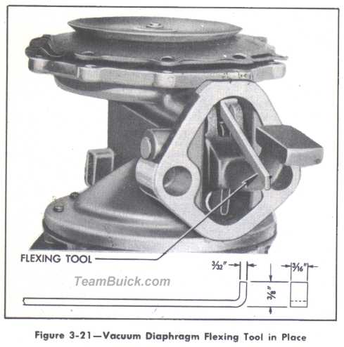
7. Depress rocker arm and insert hooked end of Diaphragm Flexing Tool KMO-613 (AC No. PT-8) between rocker arm and the stop cast in pump body, then release rocker arm. The vacuum diaphragm will be held in a flat or level position. Se figure 3-21.
8. Place spring retainer over the riveted end of diaphragm pull rod, place diaphragm spring on the retainer, then place vacuum cover over the spring. Make sure that retainer stays down in place against the diaphragm protector.
10. Remove the flexing tool. The pressure of the vacuum spring will then flex the diaphragm the correct amount.
11. Tighten all cover screws alternately on diametrically opposite sides, turning each several turns at a time, until all are securely tightened.
f. Testing Repaired Fuel and Vacuum Pump
Bench tests of the fuel and vacuum sections of teh pump require equipment which is not available in service stations; therefore, tests must be made after installation of pump assembly on an engine. Test fuel section of pump as described in paragraph 3-15. Test vacuum section of pump as described in paragraph 3-16.
| Buick Fuel and Vacuum Part Numbers | ||
| 1523518...1 | 1936, 37, 38, 39 | 60, 80, 90 |
| 1523518...1 | 1940 | 40, 50 up to engine 44034048 on 40 Series 54034048 on 50 Series |
| 1523529...1 | 1940 | After engine 44034048 on 40 Series 54034048 on 50 Series |
| 1523529...1 | 1941 thru 1951 | 40, 50 |
| 1523520...1 | 1940 | 60, 70, 80, 90, Up to engine 64019936 on 60 Series 74019936 on 70 Series 84019936 on 80 Series 94019936 on 90 Series |
| 1521530..1 | 1940 | After engine 64019936 on 60 Series 74019936 on 70 Series 84019936 on 80 Series 94019936 on 90 Series |
| 1523530...1 | 1941, 42 1946 thru 1951 |
60, 70, 90 70 |
| 5592609...1 | 1946, 47, 48, 49 1952 1953 |
40, 50 For use when replacement engine #1393929 has been installed 40, 50 40 |