
|
Tech Reference Page #19
Vintage Air "sure fit" in a 64 Chevelle
Authored by Wes Vann, November 26, 1998
Opening comments;
You may have seen this before! I wrote the article that was in the November (98) Chevy High Performance magazine. This is NOT a reprint!
This will cover the installation of a Vintage Air "sure fit" air conditioner system. The "sure fit" kits are specific to a certain year or style car. Obviously, they are only for the popular cars, luckily my 64 is considered "popular".
Due to there being different kits for various years, I can't quote or comment on the installation on other years (other than 64 and 65).
The basic fact is that I was very impressed with the Vintage Air kit. Nothing is perfect, but it's everything within reason (Free installation would be nice).
The web site of Vintage Air can be reached by clicking here.
What you need to know and preliminary comments;
1) You can get kits for R12 or HFC-134a. Don't even think about running the R12! There isn't any advantage that I can think of and it's just going to get more difficult to get (read that as costly).
2) This isn't going to be a "restoration" kind of thing.
3) My car doesn't have the stock short water pump and the alternator is mounted on the passengers side. (the brackets are from a 69 Camaro) This is different from the "stock" configuration. Due to using the long water pump, I deleted the spacer box that is between the radiator and radiator core support.
4) My car was a non-AC car.
5) It's possible to remove the Vintage Air kit and put the car back to stock! Just keep all of the original parts in a box.
6) The kit replaces the original heater core with a new one that is integral with the AC unit that mounts under the dash. The result is a "flush" firewall (great for those 502 guys!). The windshield defroster and heater works in the same fashion as the original.
Disassembly;
Remove the stock heater. Dang, that sounds easy!
Start with removing the water hoses. I'd recommend that you use an air hose to blow out all of the water that is within the core. If you don't do this, it will get all over the carpet inside the car. (rusty water on new carpet, ick)
In order to remove the heater box from the engine side of the firewall, you will have to drop the passenger side inner fender. You don't have to remove the fender!
The reason you have to lower the inner fender is so that you can get to the bolts that hold on the original fan motor that is mounted under the fender. You'll find that some of the nuts are covered with undercoating. As a result, they do a great job of hiding. Once all the nuts are removed, the unit can be pulled free of the sealer and removed.
You will also find that there is a wire that goes to the fan motor. This wire is disconnected and isn't used. (I cut off the connector and just taped up the wires so that they will not short out to anything)
Remove the glove box (they give you a new one that is smaller).
Remove the heater unit from inside the car. You will have to remove the pull cables from the heater control and also the electrical connector (it's a three wire connector).
Remove the heater control assembly.
Compressor;
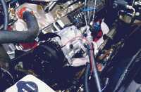
This photo shows how I mounted the compressor. It's not in what would be the stock location for a 64 and is on the drivers side.
The kit includes all of the brackets for mounting the compressor. When I ordered the kit, I let them know that I was using a long water pump and that I wanted the compressor to be mounted on the drivers side. The brackets are from Alan Grove and the quality is real impressive. One really nice thing is that they include the spacers needed if you are running headers.
I ended up having to do some minor grinding in order to clear one of the header pipes (real minor thing!)
One of the things that should be noted in the above photo is the oil fill plug on the compressor (the black plug). The compressor has to be mounted so that it's within 90 degrees from straight up. The reason has to do with keeping the oil within the compressor. I don't know what would happen if you temporarily (while removing the engine) rotated it farther. I'll have to check.
Another thing to note is that the AC hoses are going toward the drivers side front of the car. I didn't want to run them over the engine (it's a street rod kind of thinking). They go under the drivers fender, behind the headlights, and then under the radiator.
Condenser;
Normally the condenser (that radiator like thing) would be mounted within the spacer box between the radiator and the core support.
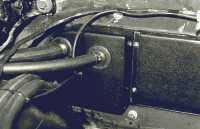
Due to my not having the spacer box (it's another one of the changes due to using the long water pump), I had to mount the condenser within the opening in the core support. (I was amazed to find that it fits!)
I removed the mounting brackets from the condenser and rebent them so that the condenser was mounted where I wanted it. Thinking about it latter, I think that I could have just removed them and turned them around (live and learn).
The condenser brackets use the same bolts that hold on the radiator and I made up studs so that it was easier to position everything and then just add nuts. If I pull the radiator, the studs keep the condenser in position.
Hoses;
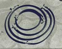
Normally Vintage Air provides the hoses already assembled, however, due to how I wanted to route the hoses, I had to modify them. (one I had completely made from scratch)
Vintage Air supplied the hoses that went to the compressor "long" and with only one fitting attached, per hose. They also provided the other fittings. The idea was that once I figured out the length (and cut off the extra), I'd just have the other fittings crimped on.
It wasn't until I got everything mounted that the idea of running the lines in front of the core support came up. (In other words, it was my fault for not thinking out all of the possibilities)
In having hoses made up, you have to keep in mind that you have to use the correct type hose and fittings for the type of refrigerant used. It takes a special machine to do the crimping! I managed to find a local shop that specializes in AC installations that was willing to make up the hoses as I wanted.
Another thing to think about is that the fittings have an angle to them (some 90 degrees, others are 45 degrees). The fittings don't rotate on the hose! As a result, the fittings have to be "clocked" correctly.
In order to make the hose, I got some standard heater hose (5/8") and routed it where the AC line was going to go. I marked the hose and then removed it. I then measured the required length.
I went to the AC shop and had the hose made up with only one fitting attached and an extra foot of length. It was installed in the location that I wanted and the exact length marked. At that time, I also marked the "clocking" or "phasing" of the fitting.
Then it was back to the AC shop to have the fitting crimped on, being careful that it was rotated as marked.
Water heater hose and control valve installation is straight forward. The only thing worth commenting on is that Chevy uses two different size hoses and the Vintage Air kit only uses 5/8". As a result, you have to replace one of the hose fittings on the engine.
There are two vacuum lines that have to be hooked up. One has to come from a vacuum source at the rear of the intake manifold. I just got a "T" fitting and hooked it up to the line that goes to the transmission. The other goes to the hot water control valve.
Mounting the Under Dash Unit;
After removing the stock unit, there are two large openings in the firewall. There are also the two openings where the water lines went.
The opening where the original fan was mounted is filled with a round plastic plate. This opening is under the fender and once the block-off plate is mounted, you can reattach the inner fender. Use silicon sealer around the edge of the block-off plate.
The other large opening and also the holes for the water lines are covered with one plastic plate. When I did it, I placed masking tape on the surface and temporarily mounted it. I used a pen and marked where the holes for the water lines were. Then I removed the plate, cut along the marks and removed all of the tape except for where the holes were present. This allowed me to put silicon sealer in the areas that would touch the firewall, but not where it would just come out the holes for the original water lines. (I ended up having to do some trimming on the plastic piece in order to get it to fit. I think that it's due to inaccuracies in Chevy making the car and not Vintage Air)
This photo shows the main cover plate (from the engine side of the firewall).
It should also be noted in this photo how the upper two hoses go off to the left. They are the AC lines (the other two are the water lines) and they dodge between the outer fender and the inner fender. This keeps them out of view. It also means that they became rather long!!
Mounting the AC unit is a two person job!! One of the attachment bolts goes through the firewall, and I tried to make it easier by using a stud in it's place. The thought was that I could get it balanced in place, then add the nut. Just make your life manageable and have somebody present to help you.
Positioning the unit is complicated by the fact that you have to align it up with the stock defroster ducts that are under the dash. Plan on taking your time, and it's "do-able".
Other than the bolt through the firewall, there are two other attachment points for the AC unit.
Controls;
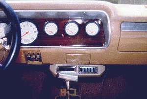
One of the really nice things about the Vintage Air kit is that the controls use the factory (non-air) control set-up. This keeps it looking more "factory".
What with the fact that I changed the color of the interior, I also had to change the color of the control unit to match.
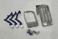
The unit is easy to disassemble by grinding off the rivets that hold it together. Once apart, I ground off all the casting flash, used DP90 primer on it, and then painted it with the same enamel paint that I used on the dash.
While the unit is apart, make sure that the switch is functioning correctly and smoothly. The switch will be used for the new units fan control.
Wires and Cables;
There is a "good point / bad point" thing about the wiring hook up.
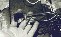
If you are into being able to convert the car back to "original", you don't have to cut any of the wiring that exists under the dash. The kit includes "buddy" clips that enable you to hook up the wiring into the electrical connector that originally plugged into the heater. If you go this route, your hook-up would be as shown in the photo below. I'd recommend that all wiring be "tie-wrapped" so that stuff doesn't work loose. Then wrap it with electrical tape.
I chose to modify the wiring for simplicity should I have to remove the unit. (I have already made a ton of changes to the wiring, so there isn't any way that it's going back to stock)
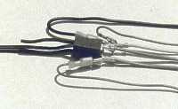
I used standard "three connector" trailer electrical connectors. This makes it easy to disconnect should I have to remove the unit. The photo below shows one of the connectors.
Only two of the original pull cables are used. They are swapped from their original positions due to different lengths being required. Hooking them up at the AC unit is kind of a pain. It's a problem what with the fact there really isn't a ton of spare room under the dash. Take your time and keep a cool head!
Vents;
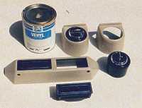
The vents that are provided with the kit get mounted under the dash. The housings come black and the vents are removable.
I used PPG Vinyl dye to paint the housings to match the color of the dash. The vinyl dye can be color matched to any color that is needed.
To be honest, I really don't like the side vents (the single vent units). They have too much of an "add-on" look and when I manage to find some factory vents, I'll change them. I can't blame Vintage Air! It's not their job to provide "restoration" parts.
The routing of the hoses that hook up to the vents is straight forward except for the one that goes adjacent to the passengers door. All I can say is to carefully follow the path called out in the directions. It seems to go all over the place, but it ends up where it should. (I spent quite some time thinking that I could come up with a better path, and there just isn't any other way!)
The finishing tid-bits and items; (not in any particular order)
1) You have to replace the stock fuse with a 30 amp one. I forgot this and when I was having the unit charged, blew out the smaller one. I had to "borrow" one in order to finish the charging. Boy, did I feel dumb!
2) You have to install the new glove box that they provide. It's smaller and the original one will not fit. Heck, the only gloves I have are welding gloves.
3) You have to run a drain line from the base of the AC unit through the firewall.
4) One of the items they don't provide is the fan belt. I spent quite some time going back and forth to the auto parts store finding one that was exactly the size I wanted. Use only Gates belts! In my mind, they are the best.
5) It's a no brainer, but, they don't provide the refrigerant and you have to go to a shop to have the system evacuated and then charged. The shop will charge you for the service and also for the amount of refrigerant that they put in your system.
6) You have to run wires to the "binary" switch (mounted on one of the AC hose lines) and also to the compressor.
7) The AC temperature control switch is mounted on the AC unit under the dash. It is out of view and reachable. At first, this seemed rather strange, however I don't ever plan on changing the setting. The option would be to move the switch to the center vent housing.
8) When attaching the hoses to items like the condenser, always use two wrenches! If you don't, you could damage the condenser.
Closing comments and further ideas;
1) I like how I managed to route the AC lines in the engine compartment, however I could have been even more trick. It would be nice to have the lines that go in front of the radiator core support done in stainless hardline. I'm going to do it! I just don't know when.
2) Currently, the dryer is partially blocking the air flow through the condenser and radiator. When I do the hardlines, I'll relocate the dryer off to the side.
3) I think that it would be possible to have the hoses (AC and water) go through the original fan opening in the firewall (under the fender). You would have to make up a bulkhead fitting due to the limited accessibility in this location. It wouldn't be that hard if you were willing to remove the fender while doing it. The water lines could then be run from the engine, downward, and then between the inner and outer fenders, hiding them from view as much as possible.
4) While I was doing all this, I replaced the firewall insulation pad. Now is the time to do it!
Good luck and be careful!
